+


433Mhz Remote Control Switch for Light,Door, Garage Universal Remote AC 85V ~ 250V 110V 220V 2CH Relay Receiver and Controller
433Mhz Remote Control Switch for Light,Door, Garage Universal Remote AC 85V ~ 250V 110V 220V 2CH Relay Receiver and Controller
Include
Package 1 include 1PCS remote and 1PCS receiver Package 2 include 2PCS remote and 1PCS receiver Package 3 include 1PCS receiver Package 4 include 1PCS remote
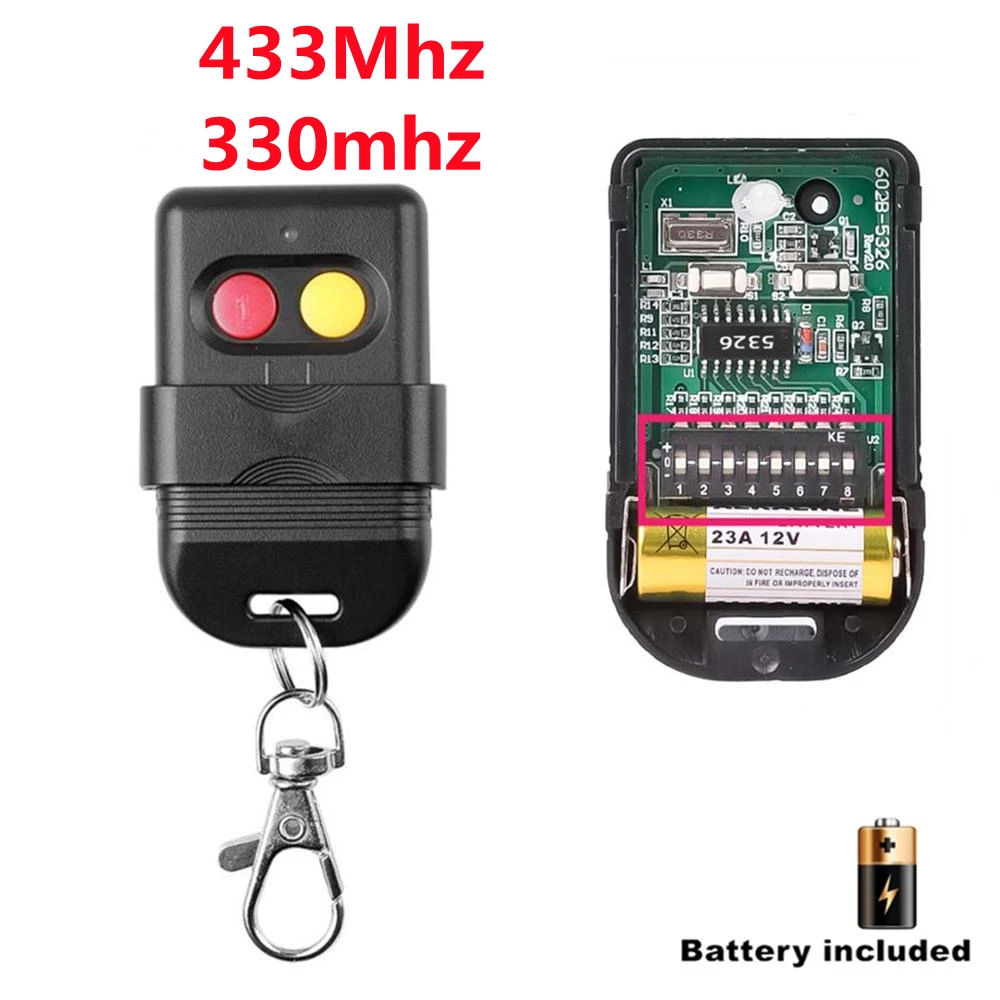
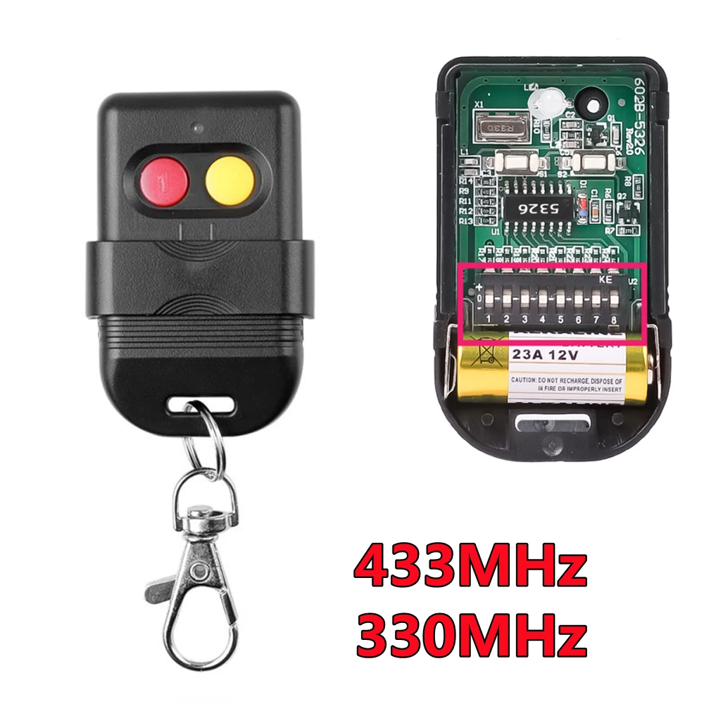
Specifications Of The Transmitter:
Model Number : SMG-004Operating Frequency: 433MHzPower by 3V Coin Cell Button Battery (Battery included )Material: PVCButton: 2 ButtonsSize: 59mm x 28mm x 8mmOperating Voltage: 3V Operating Current: 12mATransmitting Power: 10mwModulation Mode: ASK (AM)Encoding Type: LearningTransfers Distance: 20-50 m
Specifications Of The Receiver:
Model Number : SMG-802-220VProduct Type: Dual Channel Remote Control SwitchEncoding Type: Intelligent Learning CodeRF Working Mode: Superheterodyne ReceptionModulation Mode: ASKWorking Mode: Momentary, Toggle and Latching Mode.RF Frequency: 433MHzInput Voltage: AC 85V~250VStandby Current:<8.5mAReceiving Sensitivity: >97dbmRemote Control Range: >50m (Free Space)Wired Connection Way: Fixed Wiring PillarOutput Terminal: NO, COM, NCOn-off Output (Wire Port): NO(Normal Open), COM(Commonality End), NC(Normally Closed End).Color: Green (PCB Board), White (Outside Shell)Circuit Board Size: 7.3 * 5.2 * 2.5cm

Circuit Connection modes
Please Note:the Receiver Switch Module part have 2 ways of working mode.The OUTPUT signal has 2 Voltage Level. It decided by the INPUT of the COM pin.
OUTPUT mode 1
Connect the COM to the Power Supply by AC 85-250V, the Output pin will create AC 85-250V Signal.Please check below diagram for better understanding.

OUTPUT mode 2
Connect the COM pin with any other Additional Power Supply,the output will create the same Voltage signal as the Additional Power Supply. it can be Direct Current or Alternating Current. Decided by the Additional Power Supply.BUT, Please note: the additional Power Supply should be in the range of the Receiver Switch Module-(DC5-12V, AC 85-250V).Please check below diagram for better understanding.

Wiring diagram example


About Working mode:
Momentary:Push the remote button , the relay connects, release the remote button , the relay dis-connects.Toggle:Push once the remote button , the relay connects , push twice the remote button , the relay dis-connects.Interlock:Push the remote button A ,frist relay connects ,Push the remote button B ,the second relay connects and frist relay dis-connects.When you Push button A again ,frist relay connects and the second relay dis-connects.Push other remote button,frist relay and the second relay all dis-connect.
Set up : Momentary Mode
STEP 1Press the learning button on the Receiver board once.Wait for a moment , the LED will turn off , indicating you entered the learning state. STEP 2Press one button on the Remote Control , the LED on the receiver board will flash on then off indicating the button was learned. STEP 3Press another button on the Remote Control, watching the LED go on and off again.Wait 3 seconds, the LED will turn on again, indicating system is ready for use.
Set up :Toggle Mode
STEP 1Press the learning button on the Receiver board twice.Wait for a moment , the LED will turn off , indicating you entered the learning state. STEP 2Press one button on the Remote Control, the LED on the receiver board will flash on then turn off , indicating the button was learned. STEP 3Press another button on the Remote Control , watching the LED go on and off again.Wait 3 seconds, the LED indicator will turn on again , indicating system is ready for use
Set up : L atched Mode
STEP 1Press the learning button on the Receiver board 3 times. STEP 2Press one button on the Remote Control, STEP 3Press another button on the Remote ControlWait 3 seconds, the LED indicator will turn on again , indicating system is ready for use On this products details page, there is a demonstration video available.
Delete the existing data about remote mode
Note: When you receive our products, it maybe set in one remote mode randomly, that because each product got test when it can be arranged to shipment.So, please delete the existing data about remote mode for the first application. Press the learning button on the Receiver Switch Module board 8 times , the existing data are deleted successfully. After deleted the data, all the remote control cannot work any more.
*If you do not understand. Please use the computer to view the video in the product details page or send us a message.*
Brand Name : Scimagic-RC
Frequency : 433 MHz
Wireless Communication : RF
Package : Yes
Support APP : No
Channel : 2
Certification : CE
Use : Universal,Lighting,Electric Door,Automated curtains,SWITCH
Model Number : SMG-802
Origin : Mainland China
Support remote type : Learning code (1527)
Receive sensitivity : >97dbm
Standby Current : <8.5MA
Decoding mode : MCU software decoding
Wiring type : fixed terminal
Remote storage : 16pcs
Input Power : DC12V 24V AC 85V-250V
Working mode : Momentary,Toggle,Interlock
RF working mode : superheterodyne