+


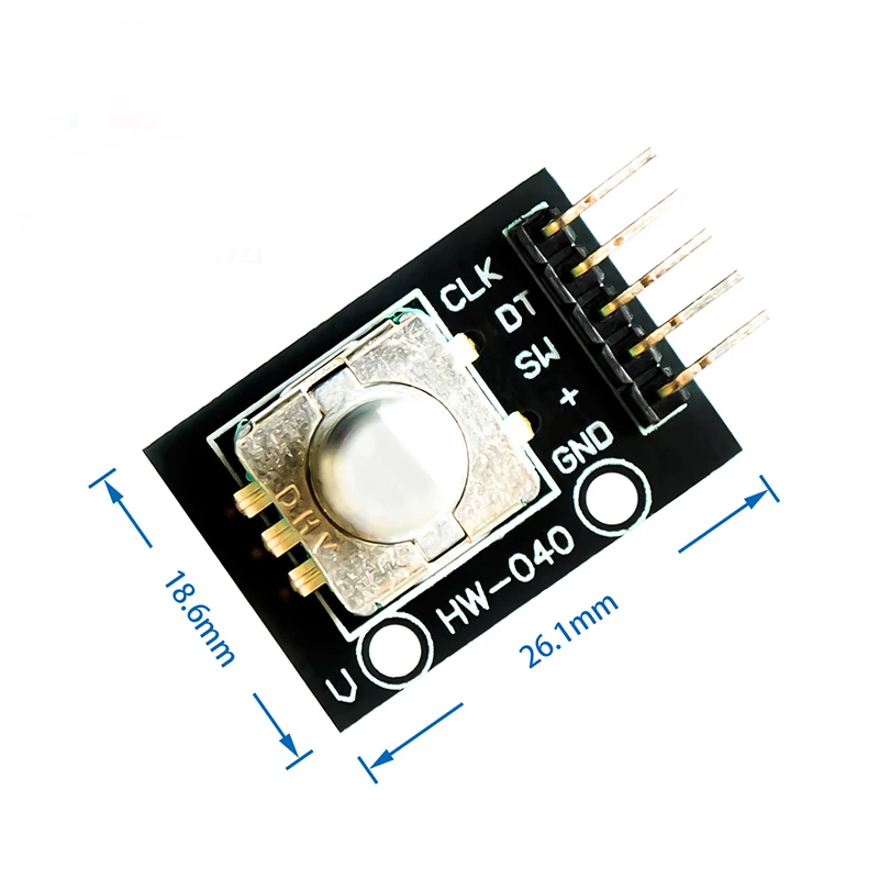
KY-040 360 Degrees Rotary Encoder Switch Module, Brick Sensor Switch Development KY040 Potentiometer knob Kit for arduino
Material: Electronic components + PCB Size: About 31 * 19 * 29mm / 1.22" * 0.75" * 1.14" Main color: Black Working voltage: 5V

 Rotary encoders can count the number of pulses output during forward and reverse rotation through rotation. Unlike a potentiometer, the rotation count is not limited. With the buttons on the rotary encoder, it can be reset to the initial state, that is, counting from 0.
working principle:
Incremental encoder is a rotary sensor that converts rotational displacement into a series of digital pulse signals. These pulses are used to control angular displacement. The angular displacement conversion in the Eltra encoder uses the photoelectric scanning principle. The reading system is based on the rotation of a radial index disk (code disk) composed of alternating light-transmitting windows and opaque windows, and is illuminated vertically by an infrared light source at the same time, and the light projects the image of the code disk onto the surface of the receiver . The receiver is covered with a layer of diffraction grating, which has the same window width as the code disc. The job of the receiver is to sense the changes produced by the rotation of the disc, and then convert the light changes into corresponding electrical changes. Then make the low-level signal rise to a higher level, and produce a square pulse without any interference, which must be processed by electronic circuits. The reading system usually uses a differential method, that is, two different signals with the same waveform but a phase difference of 180° are compared in order to improve the quality and stability of the output signal. The reading is formed on the basis of the difference between the two signals, thereby eliminating interference.
Incremental encoder:
Incremental encoders give two-phase square waves, their phase difference is 90°, usually called A channel and B channel. One of the channels gives information related to the rotation speed. At the same time, the two channel signals are compared sequentially to obtain the information of the rotation direction. There is also a special signal called Z or Zero Channel, which gives the absolute zero position of the encoder. This signal is a square wave that coincides with the center line of the A channel square wave.
Rotary encoders can count the number of pulses output during forward and reverse rotation through rotation. Unlike a potentiometer, the rotation count is not limited. With the buttons on the rotary encoder, it can be reset to the initial state, that is, counting from 0.
working principle:
Incremental encoder is a rotary sensor that converts rotational displacement into a series of digital pulse signals. These pulses are used to control angular displacement. The angular displacement conversion in the Eltra encoder uses the photoelectric scanning principle. The reading system is based on the rotation of a radial index disk (code disk) composed of alternating light-transmitting windows and opaque windows, and is illuminated vertically by an infrared light source at the same time, and the light projects the image of the code disk onto the surface of the receiver . The receiver is covered with a layer of diffraction grating, which has the same window width as the code disc. The job of the receiver is to sense the changes produced by the rotation of the disc, and then convert the light changes into corresponding electrical changes. Then make the low-level signal rise to a higher level, and produce a square pulse without any interference, which must be processed by electronic circuits. The reading system usually uses a differential method, that is, two different signals with the same waveform but a phase difference of 180° are compared in order to improve the quality and stability of the output signal. The reading is formed on the basis of the difference between the two signals, thereby eliminating interference.
Incremental encoder:
Incremental encoders give two-phase square waves, their phase difference is 90°, usually called A channel and B channel. One of the channels gives information related to the rotation speed. At the same time, the two channel signals are compared sequentially to obtain the information of the rotation direction. There is also a special signal called Z or Zero Channel, which gives the absolute zero position of the encoder. This signal is a square wave that coincides with the center line of the A channel square wave.  The accuracy of incremental encoders depends on mechanical and electrical factors. These factors are: grating indexing error, disc eccentricity, bearing eccentricity, errors introduced by the electronic reading device, and the inaccuracy of the optical part. The measurement unit to determine the accuracy of the encoder is the electrical degree, and the accuracy of the encoder determines the pulse division of the encoder. The following uses 360° electrical degrees to represent the rotation of the mechanical shaft, and the rotation of the shaft must be a complete cycle. To know how much mechanical angle is equivalent to electrical 360 degrees, you can use the following formula to calculate: electrical 360 = mechanical 360°/n° pulse/
 Turn to the picture: A and B reversing signal
The encoder indexing error is expressed by the maximum deviation of two continuous pulse waves in electrical angles. Errors exist in any encoder, which is caused by the aforementioned factors. The maximum error of the Eltra encoder is ±25 electrical degrees (under any conditions that have been declared), which is equivalent to a nominal value deviation of ±7%. As for the phase difference of 90° (electrically), the maximum deviation of the two channels is ±35 The electrical degree is equivalent to about ±10% deviation of the rated value.
UVW signal incremental encoder
In addition to the above-mentioned traditional encoders, there are some incremental encoders integrated with other electrical output signals. The incremental encoder integrated with the UVW signal is an example, and it is usually used in the feedback of AC servo motors. These magnetic pole signals generally appear in AC servo motors, and UVW signals are generally designed by simulating the function of magnetic components. In the Eltra encoder, these UVW signals are generated optically and appear in the form of three square waves, which are offset by 120° from each other. In order to start the motor, the starter used to control the motor needs these correct signals. These UVW magnetic pole pulses can be repeated many times in the rotation of the mechanical shaft because they directly depend on the number of poles of the connected motor and are used for UVW signals of 4, 6 or more pole motors.
Turn to the picture: A and B reversing signal
The encoder indexing error is expressed by the maximum deviation of two continuous pulse waves in electrical angles. Errors exist in any encoder, which is caused by the aforementioned factors. The maximum error of the Eltra encoder is ±25 electrical degrees (under any conditions that have been declared), which is equivalent to a nominal value deviation of ±7%. As for the phase difference of 90° (electrically), the maximum deviation of the two channels is ±35 The electrical degree is equivalent to about ±10% deviation of the rated value.
UVW signal incremental encoder
In addition to the above-mentioned traditional encoders, there are some incremental encoders integrated with other electrical output signals. The incremental encoder integrated with the UVW signal is an example, and it is usually used in the feedback of AC servo motors. These magnetic pole signals generally appear in AC servo motors, and UVW signals are generally designed by simulating the function of magnetic components. In the Eltra encoder, these UVW signals are generated optically and appear in the form of three square waves, which are offset by 120° from each other. In order to start the motor, the starter used to control the motor needs these correct signals. These UVW magnetic pole pulses can be repeated many times in the rotation of the mechanical shaft because they directly depend on the number of poles of the connected motor and are used for UVW signals of 4, 6 or more pole motors.
Origin : CN(Origin)
Supply Voltage : 5V
Model Number : KY-040 360 Degrees Rotary Encoder Module
Package : SMD
Application : Computer
Dissipation Power : standard
Operating Temperature : standard
Condition : New
is_customized : Yes
Type : Voltage Regulator
1 : KY-040 Encoder Module
4 : KY-040 for arduino
2 : 360 Degrees Rotary Encoder Module
3 : Encoder knob